
To repair a mesh in Rhino, preserve the original, diagnose the working copy, repair the specific defects you find, and recheck the result. Then export only the intended geometry, re-import the STL into a separate document, and inspect its dimensions and slice preview in the intended slicer.
This independently written guide uses Rhino 8 documentation as its baseline. It concerns an existing polygon mesh: a shape defined by vertices and polygon faces. Rhino meshes can contain triangles and quadrilaterals. Repairing that structure is a different task from repairing the surfaces, trims and joins of a NURBS polysurface. Rhino 8 mesh documentation
1. Preserve the original and define what must survive
Save an untouched source file and work on a separate copy. Keep the reference available for comparison, but exclude it from the eventual export selection.
Before editing, note the model units, overall dimensions and any critical features: hole diameters, thin walls, mating surfaces, clearances and small details. Identify which openings are intentional. These references help you judge whether a cleaner mesh still represents the design.
If the source is a NURBS surface or polysurface that needs repair before meshing, use Drawnscale’s geometry QA guide for that work. The mesh commands below address polygon geometry.
2. Diagnose before changing geometry
Select the working mesh and run Check to examine its data structure. Then run MeshRepair and use Check Mesh to view its reported problems, including duplicate faces, collapsed geometry, non-manifold edges and inconsistent normals. Treat the findings as a repair list, rather than selecting every available action automatically. Check documentation, MeshRepair documentation
Use ShowEdges to locate naked edges, which are open mesh boundaries, and non-manifold edges, which are shared by more than two faces. Choose the relevant edge display and inspect each highlighted region. This locates connectivity problems; it does not establish that every face is correctly oriented or that the mesh has no self-intersections. ShowEdges documentation
Keep the validation terms separate:
- Valid mesh object: its data structure passes the relevant object check. That is a limited diagnostic result.
- Closed mesh: it has no naked boundary edges.
- Manifold topology: the faces form a locally coherent surface without branching connections. For a closed manifold surface, each edge is shared by exactly two faces. McNeel documents the edge-sharing criterion separately; passing that criterion alone is not a complete geometry assessment. Manifold edge definition
- Correct orientation: face directions consistently distinguish the material from the surrounding space.
- Suitable for printing: the geometry also meets the requirements of the chosen process, material and machine.
Here, watertight means a closed boundary around the intended material, with no gaps through that boundary. It is a closure requirement, not a certificate of correct shape, orientation or manufacturability. Rhino’s STL documentation uses the term for completely closed polygon meshes. STL documentation
3. Apply targeted repairs and check their effects
Close missing mesh patches while preserving designed openings
A missing patch leaves a boundary where faces should exist. An intentional opening can be part of a fully closed material boundary. A through-hole has a wall connecting its entrances; a hollow vessel with wall thickness has inner and outer surfaces connected around its rim. The passage or mouth stays open while the material itself is enclosed.
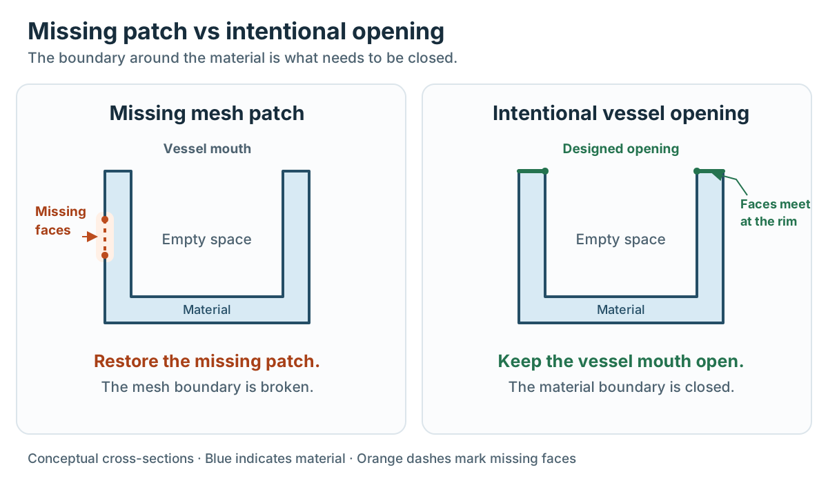
A single surface representing only the vessel’s exterior is different: its rim may be a naked boundary because the inner wall and connecting faces are absent. Capping that rim would change the design instead of completing the intended wall geometry.
When a boundary represents a genuinely missing patch, use FillMeshHole and select that hole boundary. Its JoinMesh option joins the added faces to the original mesh. FillMeshHoles instead fills all holes in the selected polygon mesh with triangular faces. Choose the all-hole operation only after reviewing every boundary it would close. Hole-filling documentation
Adding faces can close a boundary without recovering its intended contour. Compare the patch with the reference shape and critical clearances.
In Rhino 3D’s mesh-repair tutorial at 1:38–2:18, recorded using Rhino 8 WIP, Kyle Houchens explains why a straightforward fill of a missing corner gives an unwanted shape: geometry defining the corner is needed before meshing to it. His explanation illustrates the difference between closing a hole and restoring the intended form.
Remove duplicate and degenerate faces
Duplicate faces repeat a face in the mesh. Use MeshRepair’s duplicate-face action to remove the reported duplicates. MeshRepair documentation
Degenerate faces have zero area, while degenerate edges have zero length. CullDegenerateMeshFaces removes these elements and any vertices orphaned by their removal; its documentation notes that unwelded vertices remain. MeshRepair also provides collapsed-face and zero-length-edge actions. CullDegenerateMeshFaces documentation, MeshRepair documentation
Removing unusable elements can expose boundaries; it does not reconstruct the surrounding shape.
Resolve non-manifold connections deliberately
MeshRepair’s documented non-manifold action extracts the affected faces. It does not choose the correct solid boundary for you. The related ExtractNonManifoldMeshEdges command also extracts faces with non-manifold edges from a mesh. MeshRepair documentation, Extraction documentation
Inspect both the extracted faces and the remaining mesh. Extraction can include faces that belong to the intended wall, so identify the unwanted geometry before removing anything.
Hypothetical example: an unwanted hanging face. Suppose an otherwise closed mesh has a triangular flap attached to a wall. Its attachment edge is shared by three faces—the two wall faces and the flap—while the flap’s other edges are naked. The design reference confirms that the wall should be continuous and the flap should not exist.
For this example, use ExtractNonManifoldMeshEdges with ExtractHangingFacesOnly=Yes and MinimumFaceCount=3. The first option limits extraction to faces with both non-manifold and naked edges; the second includes the three-face attachment edge. Compare the extracted flap with the reference, then remove that unwanted object from the working copy. These settings describe this example, not every non-manifold defect. Extraction options
Run ShowEdges on the remaining wall mesh in both naked-edge and non-manifold modes, then repeat Check Mesh. If the attachment defect has disappeared, the wall remains closed and its contour is unchanged, removal has addressed this local problem. If extraction also removed needed wall faces, retain them and restore the intended boundary before accepting the repair.
For other cases where unwanted faces remain in the mesh, DeleteFaces removes selected mesh faces. Deleting part of a genuine wall leaves an opening that still needs reconstruction. DeleteFaces documentation
Make normals consistent, then check their overall direction
A face normal indicates a face’s front direction. Inconsistent normals mean neighboring faces disagree about orientation. UnifyMeshNormals makes their directions consistent; it does not establish the correct overall direction. McNeel’s instructions specify a single unjoined mesh, so start with one mesh piece at a time. UnifyMeshNormals documentation
One selectable object is not necessarily one connected mesh: Join can combine mesh pieces that do not touch. Joining also differs from welding, which merges coincident vertices along eligible edges. An assembly collected into one object may still contain separate parts whose orientation needs attention. Join documentation, Mesh welding explanation
Inspect the result using a display mode that distinguishes front and back faces. Rhino’s Shaded display settings support a separate backface color and backface culling. Look around the model, including recesses and cavity walls, rather than judging one viewpoint. Shaded display documentation
For a solid boundary, normals should point away from the material: toward the exterior on outside walls and into empty space on cavity walls. If the mesh is consistently reversed, Flip reverses its normal direction. Flipping the whole object will not resolve a mixture of correctly and incorrectly oriented faces. Flip documentation
If UnifyMeshNormals appears ineffective on an assembled mesh, McNeel’s documented fallback is to use Explode, correct the resulting pieces, then rejoin them. For meshes, Explode separates parts along unwelded edges. Run UnifyMeshNormals on the resulting pieces, inspect their front/back orientation, and use Flip on any consistently reversed piece before using Join where the pieces are intended to form one object. Documented fallback, Explode documentation
A fully unwelded mesh can explode into one object per face, greatly increasing memory use; this makes the fallback unsuitable as a routine step for a dense mesh. Rejoining also does not prove closure or manifold topology, and Rhino can align nearby naked mesh vertices within the document tolerance. Include the rejoined result in the final geometry checks below. Explode limitations, Join behavior
Check self-intersections separately
Self-intersections occur where portions of a mesh cross through one another. A mesh can have closed edge connections and still contain this problem.
Run MeshSelfIntersect on the suspect mesh. It creates polylines at self-intersections, giving you locations to inspect; it does not remove the crossings or repair the mesh. MeshSelfIntersect documentation
If the crossing comes from an unwanted patch, selective face deletion may be part of the repair; any resulting opening still needs a boundary matching the intended shape. Consider ShrinkWrap when reconstruction is acceptable. If both crossing regions are needed, establish how they should meet from the design reference before changing them.
Troubleshooting reference
Match the finding to the repair approach described above.
Scroll the table horizontally to read every column.
| Symptom or finding | Diagnostic check | Repair approach | Limitation or follow-up |
|---|---|---|---|
| Missing patch or naked boundary | ShowEdges: naked edges |
FillMeshHole for the reviewed boundary; FillMeshHoles only after reviewing all boundaries |
Preserve intended passages; inspect the added shape |
| Duplicate faces | MeshRepair: Check Mesh | Remove the reported duplicates | Include the result in the final mesh check |
| Reported degenerate faces or zero-length edges | MeshRepair findings | CullDegenerateMeshFaces or the relevant panel action |
Removal may expose boundaries |
| Edge shared by more than two faces | ShowEdges: non-manifold edges; MeshRepair |
Extract affected faces; remove confirmed unwanted geometry or restore needed wall faces | Hanging-face extraction is suitable only for matching defects |
| Mixed face orientation | MeshRepair findings; front/back display | UnifyMeshNormals; use the documented explode/rejoin fallback if appropriate |
Fully unwelded meshes may explode into individual faces |
| Consistently reversed orientation | Front/back display | Flip |
It reverses the selected object, including faces already pointing correctly |
| Crossing mesh regions | MeshSelfIntersect |
Inspect the marked region; choose local boundary repair or suitable reconstruction | Intersection polylines are diagnostic output |
4. Decide whether ShrinkWrap is appropriate
Use the Rhino ShrinkWrap settings and feature-check guide to connect reconstruction controls with the openings, dimensions and details that must survive.
ShrinkWrap creates a new mesh around selected geometry, including mesh inputs. McNeel lists valid closed meshes from difficult geometry and meshes without internal self-intersections among its intended uses. Treat it as reconstruction requiring review. ShrinkWrap documentation
Local repair or ShrinkWrap?
Choose local repair when defects are limited and the surrounding geometry is worth preserving. Consider ShrinkWrap when widespread damage makes local repair impractical and a reconstructed boundary is acceptable. Retain the original and compare dimensions, fine detail, gaps and intended openings before accepting the new mesh.
The controls affect the result: target edge length governs approximate output edge size, offset changes its position, and smoothing can deflate the mesh. Fill holes in input objects can close small gaps that were designed into the input. Use the preview and keep Delete input objects disabled while comparing alternatives. No universal preset guarantees preservation of your model’s shape. ShrinkWrap documentation
5. Validate the repaired mesh and exported STL
For the source-type decision, tessellation controls and receiving-file worksheet, continue with Rhino STL export settings and acceptance checks.
Recheck the working mesh
After each meaningful edit, repeat the checks relevant to that region. Before export, run a final Check and MeshRepair assessment, inspect naked and non-manifold edges, verify face orientation, and repeat the self-intersection check where relevant.
Compare the repaired copy with the preserved original and the design references for critical dimensions, silhouette, wall geometry, small features and deliberate openings. Record any intentional changes.
Export the intended selection
Select the approved mesh and use Export, choosing STL as the format. Export writes the selected objects, so review that selection for reference copies and unwanted extracted faces. Export documentation
Distinguish two inputs. When exporting NURBS geometry, Rhino creates a mesh, and tessellation controls govern that approximation. When exporting an existing polygon mesh, those NURBS meshing controls do not regenerate its detail. McNeel’s support explanation confirms this distinction. A tighter export tolerance cannot recover geometry missing from the mesh. Rhino 8 STL documentation, McNeel support explanation
Choose binary or ASCII according to the receiving workflow. Rhino warns when an exported mesh is open; proceeding through that warning does not resolve the opening. Investigate it before accepting the file. STL documentation
Re-import into a separate document
Import the saved STL into a separate Rhino document with the intended units. Record its weld-angle and disjoint-mesh import choices. Where saved units are available, Rhino displays them and can scale the imported geometry to the document’s units. STL import documentation
Confirm scale with a known dimension, rather than trusting a filename or an apparently reasonable viewport size. Recheck the imported geometry for validity, boundaries, orientation and relevant intersections. Inspect critical features again. This checks the saved artifact as interpreted on import; it does not prove that every downstream application will interpret it identically.
For packaging the source, export and validation notes, use Drawnscale’s export and handoff workflow.
Inspect the intended slicer’s interpretation
Load that same STL into the slicer you plan to use. Check dimensions and warnings, then inspect the layer preview through the whole model. Pay particular attention to repaired regions, thin features, holes, cavities and separate parts: do the planned layers represent the intended material?
Treat automatic slicer repairs as changes to inspect. Prusa’s documentation, for example, acknowledges automatic repair but also explains that some damaged models need further work. Compare any repaired interpretation with the accepted geometry before proceeding. Official slicer repair guidance
Geometry validation and a plausible slice preview do not prove a successful physical print. Wall thickness, clearances, build orientation and supports still need review against the chosen manufacturing process.
Final mesh and print-file checklist
- Preserve the original and identify the working revision.
- Record units, known dimensions and openings that must remain.
- Investigate validity, duplicate and degenerate faces, edge connectivity, normals and relevant self-intersections.
- Inspect the effects of each repair, including any extracted or deleted faces.
- Compare local patches or reconstructed geometry with the design reference.
- Export only the approved geometry and resolve unexpected warnings.
- Re-import the STL separately, confirm scale and repeat relevant checks.
- Inspect slicer warnings, automatic repairs and layer previews.
- Review wall thickness, clearances, orientation and supports for the intended process.
FAQs
Do I need to convert an imported STL to NURBS before repairing it?
No. STL imports as polygon mesh geometry, ready for mesh tools. NURBS conversion is a separate modeling task. STL documentation
Why can a smooth-looking mesh still produce faceted output?
Smooth display shading can conceal individual facets. Inspect with flat shading to see the faces more clearly; it changes the display, not the mesh’s geometry. Shaded display documentation
Why do naked edges remain after I fill a hole?
Check whether the added patch belongs to the mesh you are checking: FillMeshHole’s JoinMesh option joins the new faces to the original. Use ShowEdges to locate the remaining boundaries; they may be elsewhere in the model. Repair those according to their purpose rather than capping every visible opening. Hole-filling documentation, Edge diagnostics